Receiver

As the heart of the antenna, the superconducting receiver systems are being constructed in the receiver laboratory of the ASIAA. To achieve high sensitivity, several key components for the SMA receiver only exist in few research laboratories around the world, and none of the places is in our own lab prior to joining this project; to name a few: wide-band, high frequency local oscillators, wide-band multipliers at sub-millimeter wavelength, the low-noise C-band pre-amplifiers, and quasi-optics techniques.
One of the most critical processes for the SMA is to access the source of the SIS mixers. We have decided to build up our own expertise in mixer design, fabrication, and testing. The learning process has been jump-started by our partner in the SAO receiver lab. For SIS junction fabrication, it has been a collaborative effort between the ASIAA, the Material Science Center of National Tsing-Hua University (NTHU) in Taiwan, the Nobeyama Radio Observatory (NRO) of Japan, and Purple Mountain Observatory of China. Currently, the ASIAA mixers for the 200 GHz and 300 GHz bands have been installed in the antennas with very good performance. The mixer design and fabrication for the 600 GHz and higher is an on-going effort.
Receiver System Overview
 The SMA optics and receiver system were originally designed and developed in the SAO receiver laboratory. The schematic (above) shows the signal path and the key optical components, as well as the cryostat that contains the SIS receiver modules and the IF amplifier chains.
The incoming signal beam enters the receiver package from above and is separated into 2 orthogonal- polarized beams by a wire grid placed at 45 degrees to the signal path. The grid is integrated into a rotating holder that can be turned to select different receiver channels. The beam reflected off the grid is coupled to the lower frequency mixers (176-256 GHz and 250-350 GHz) while the transmitted beam is directed to the high frequency receivers.
The lower frequency signal beam then enters an optical sub-assembly built specifically for each receiver insert. This assembly contains two flat mirrors for the incoming signal, a Teflon lens for focusing the local oscillator signal, and a fine mesh to combine the RF and the LO signals. The LO module is located in the upper part of the optics assembly. After reflecting off the wire mesh, the signal beam enters the cryostat through a vacuum window on the top of the receiver insert.
Quasi-Optics
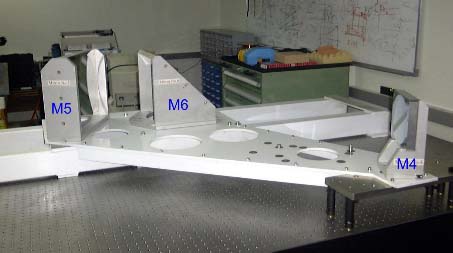
 Beam wave-guide optics is used to relay received signal to the receiver system. It consists of four metal mirrors made of aluminum (M3 not shown in the picture). The optics trains needs to be precisely aligned before their installation in the antenna. All these optics are overly sized to minimize truncation loss. This set of mirrors is located near the ceiling of the cabin. The mirrors form a beam wave-guide system to direct the incoming signal into the receiver system.
For interested reader, the paper by Dr. S. Paine et al, of SAO would be a good reference.
S. Paine et al, "Beam Waveguide and Receiver Optics for the SMA", in the Proceedings of 5th Int. Symp. Space Terahertz Tech. pp.811-823, March 1994
Receiver Module
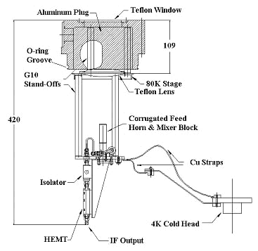
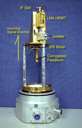
The receiver insert is designed as a plug-in unit inserted from the top of the cryostat. It is constructed in 3 sections, separated by stand-offs made of glass-fiber tubes. The room temperature part is a circular plug made of aluminum, with its center bored out for the vacuum signal window. The 80K stage is mainly a lens holder, and it makes contact with the 80 K radiation shield via a ring of BeCu spring fingers. The 4K stage is connected to the cold head through flexible pure copper straps. On the 4K stage are the SIS mixer block, followed by an isolator, and a HEMT amplifier. The HEMT operates at 5 GHz with a 2 GHz bandwidth. The IF is further amplified and filtered at the 20 K stage of the cryostat before exiting the dewar.


This photo is a real receiver insert for 178 -250 GHz channel, shown in an up-side-down sense.
Cryogenics Requirement
- Provide a 4K working environment for SIS mixer operation
- Long-term, reliable cooling in a remote observatory site
- High cooling capacity for multi-band receiver operation
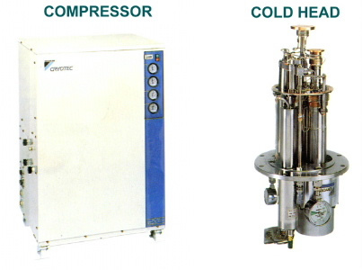
A commercial close-cycle refrigerator is used for the cooling inside the receiver. It is a three-stage cryo-cooler (4K, 10K, and 80K), and deliver more than 2.5W of cooling power at 4K. The cryo-cooler is a type of compound Gifford-McMahon (GM) and Joule-Thomson (JT) refrigerator. The GM fridge is used to pre-cool the circulating helium gas to its conversion point for the JT mechanism to kick in. This is then resulting the high cooling capacity of the fridge at 4K.


Summary For SMA Receiver System
| Frequency Coverage | 176-256 GHz |
|---|---|
| 250-350 GHz | |
| 400-520 GHz | |
| 600-720 GHz | |
| 780-900 GHz | |
| Number of receivers modules in a s ingle cryostat | 8 |
| Signal Detection / Detector | Heterodyne / SIS Mixer (Nb-Al2O3-Nb) |
| Pre Amplifier (Operation Temperature) | NRAO HEMT LNA Amplifier (4 K) |
| IF Frequency/Bandwidth | 5GHz/2GHz |
| LO Source | Gunn Oscillator / Multiplier |
| Operating Scheme | Dual-Channel Operation |
| Refrigerator | Closed-Cycle JT/GM Fridge |
| Cooling Power | > 2.5W @ 4K |


