|
Home \ Instrumentation \ Receiver \ System Overview
Receiver System Overview
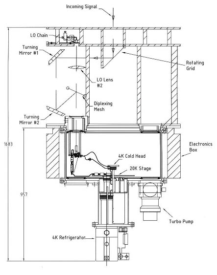
The SMA optics and receiver system were originally designed and developed in the SAO receiver laboratory. The schematic (above) shows the signal path and the key optical components, as well as the cryostat that contains the SIS receiver modules and the IF amplifier chains. The incoming signal beam enters the receiver package from above and is separated into 2 orthogonal- polarized beams by a wire grid placed at 45 degrees to the signal path. The grid is integrated into a rotating holder that can be turned to select different receiver channels. The beam reflected off the grid is coupled to the lower frequency mixers (176-256 GHz and 250-350 GHz) while the transmitted beam is directed to the high frequency receivers. The lower frequency signal beam then enters an optical sub-assembly built specifically for each receiver insert. This assembly contains two flat mirrors for the incoming signal, a Teflon lens for focusing the local oscillator signal, and a fine mesh to combine the RF and the LO signals. The LO module is located in the upper part of the optics assembly. After reflecting off the wire mesh, the signal beam enters the cryostat through a vacuum window on the top of the receiver insert. |
>> INTERNAL DOCU | ASIAA

©2014, Institute of Astronomy and Astrophysics, Academia Sinica, All Rights Reserved.
Last Updated: 2014-05-10 | Contact: web asiaa.sinica.edu.tw | Privacy and Security Policy
Last Updated: 2014-05-10 | Contact: web
